<aside> <img src="/icons/home_gray.svg" alt="/icons/home_gray.svg" width="40px" />
</aside>
<aside> <img src="/icons/send_gray.svg" alt="/icons/send_gray.svg" width="40px" />
</aside>
Getting Started (SolidWorks Plugin)
Documentation
GD&T
Learn more about GD&T tips and tricks
<aside> <img src="/icons/thought_gray.svg" alt="/icons/thought_gray.svg" width="40px" />
</aside>
For further support, contact your Drafter support representative
<aside>
</aside>
<aside>

</aside>
In the world of Geometric Dimensioning and Tolerancing (GD&T), precision is everything. The essential tool for specifying tolerances on part features is the Feature Control Frame. Whether you’re designing a critical aerospace component or a simple bracket, the feature control frame allows you to communicate how a feature should be measured and what its limits are in terms of form, orientation, location, and more. In this article, we’ll dive into what feature control frames are, why they’re vital for your engineering drawings, and how to apply them effectively.
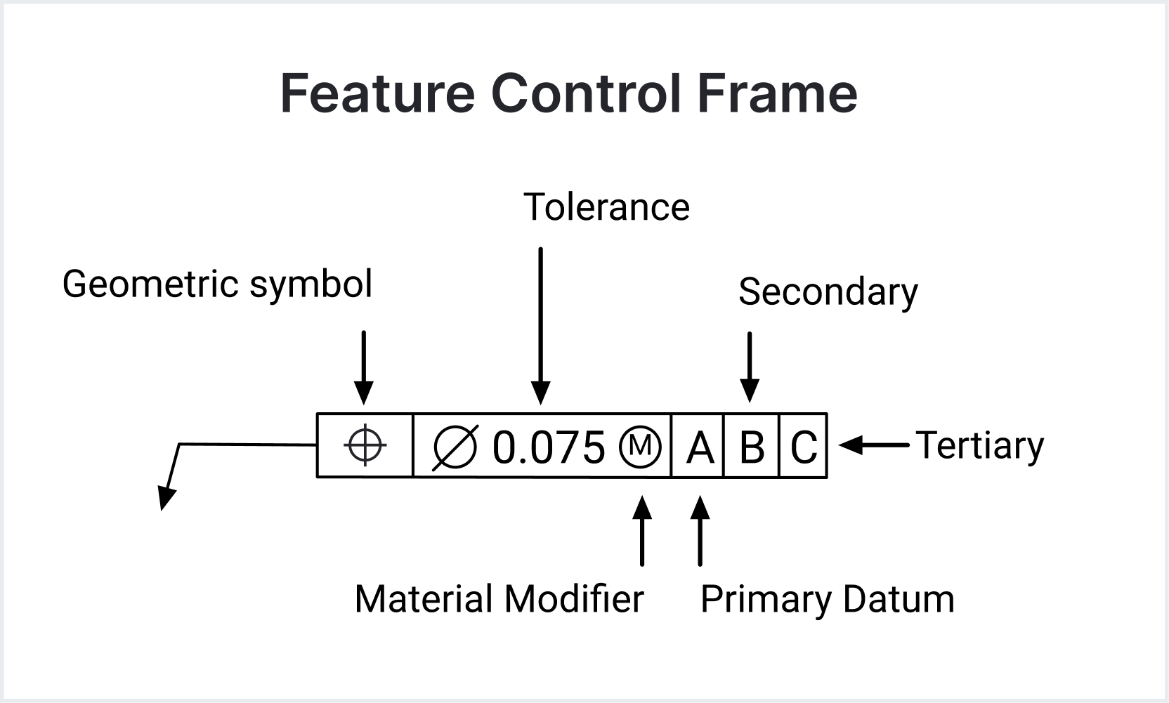
A Feature Control Frame is a rectangular box that provides all the necessary information about the tolerance for a particular feature on a part. It consists of several compartments containing symbols and numbers that communicate tolerances in a structured, universally understood way.
<aside>

Feature Control Frame Breakdown
</aside>
A typical feature control frame contains the following elements:
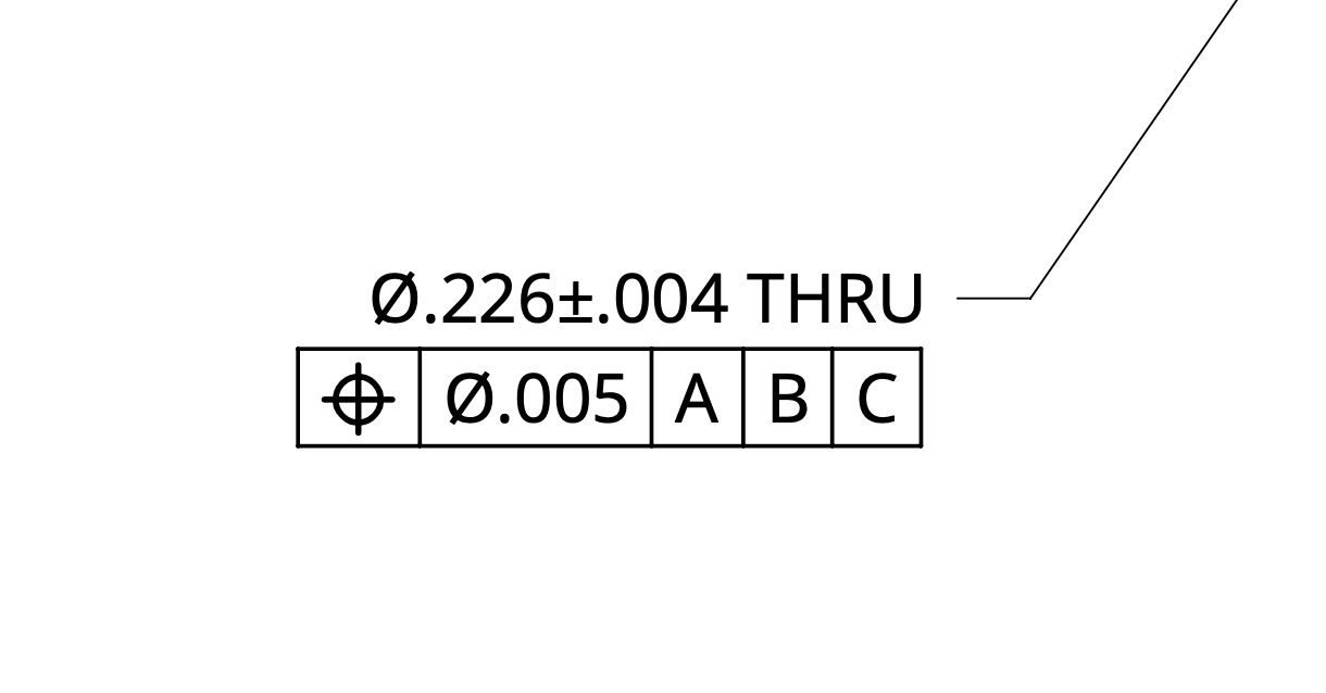
For example, if you’re controlling the position of a hole, your feature control frame will include a position symbol, the tolerance for its location, and datum references indicating how to measure that location.
<aside>

Datum Feature Control Example
</aside>
The Feature Control Frame is more than just a convenient notation system—it ensures that every part is produced and inspected to meet the required performance. It standardizes how tolerances are applied and understood across different teams, from design engineers to machinists and quality inspectors. Without this clarity, parts could be made inaccurately, leading to costly rework, assembly issues, or even product failure.
Datums play a critical role in many feature control frames. They serve as a point, line, or plane from which measurements are taken. When used correctly, datum references ensure that parts are oriented and located properly in an assembly, preventing misalignment.
For example, in a part with multiple holes, you might want each hole’s position to be relative to a central datum feature. This ensures that during assembly, all the holes align as intended. Learn more about datums here.
When adding a feature control frame to your drawing, follow these best practices to ensure clarity and manufacturability:
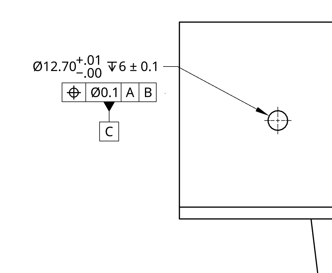
Let’s consider the case of a hole in a bracket that needs to be precisely positioned relative to the edges of the bracket.
The feature control frame might look something like this:
This tells the machinist that the hole must be within a 0.1 mm tolerance zone from the ideal location, as measured relative to the datums A, B, and C.
<aside>

Example of a Feature Control Frame for a Hole
</aside>
1. Overly Tight Tolerances
A common mistake is specifying overly tight tolerances in feature control frames, which can lead to higher manufacturing costs or parts that are difficult to produce. Always consider the capability of your manufacturing process and how critical the tolerance is to the part’s function.
2. Poor Datum Selection
Another challenge is improper datum selection. If your datums don’t reflect the true assembly conditions, you may end up with parts that are technically within tolerance but don’t fit together in the final product. Think about how the part will be used and inspected when selecting datums.
3. Communicating Tolerances Across Teams
Make sure all stakeholders understand the importance of the tolerances specified in feature control frames. Regular communication between designers, manufacturers, and inspectors ensures that the tolerances are achievable and the parts meet functional requirements.
Feature control frames in GD&T are essential for specifying and controlling part features to ensure functionality and manufacturability. By clearly communicating the required geometric characteristics, tolerances, and datum references, these frames ensure that your parts will fit together and function as intended, reducing costly errors and improving efficiency.
Mastering the use of feature control frames is a critical skill for any engineer working in precision industries. Remember to always choose the correct characteristic symbol, set appropriate tolerances, and use logical datums. By doing so, you’ll set your project up for success from design through to final production.