
<aside> <img src="/icons/home_gray.svg" alt="/icons/home_gray.svg" width="40px" />
</aside>
<aside> <img src="/icons/send_gray.svg" alt="/icons/send_gray.svg" width="40px" />
</aside>
Using the Drafter: SolidWorks Plugin
Documentation
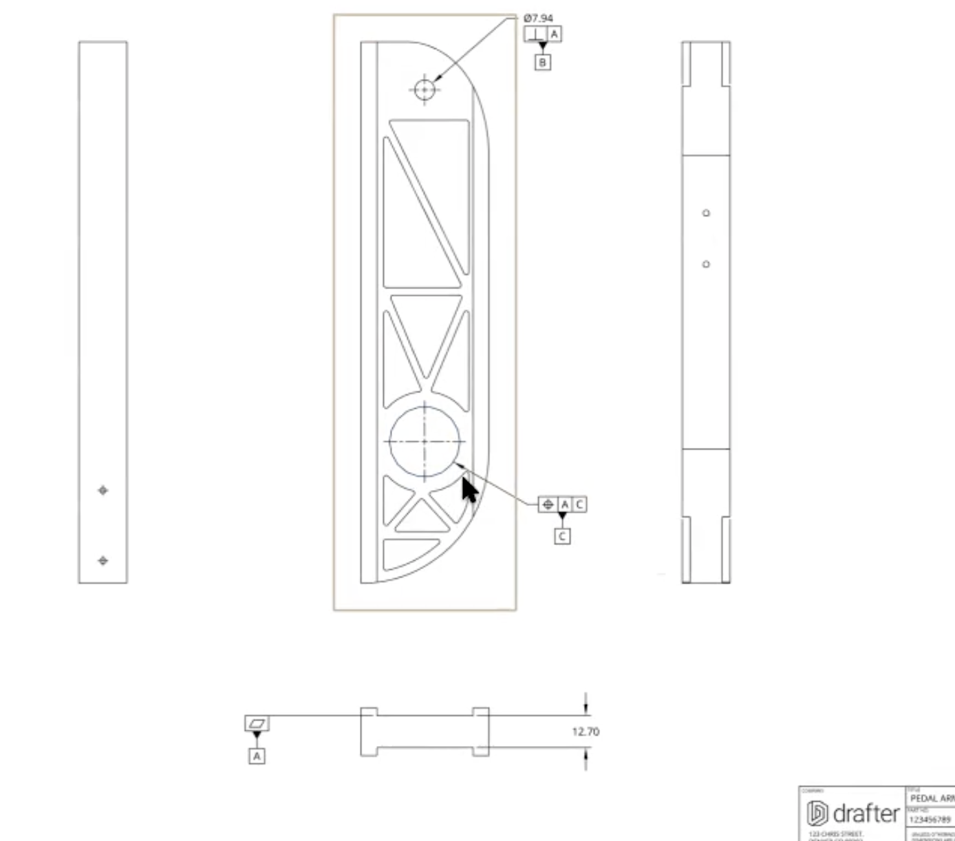
GD&T
Learn more about GD&T tips and tricks
<aside> <img src="/icons/thought_gray.svg" alt="/icons/thought_gray.svg" width="40px" />
</aside>
For further support, contact your Drafter support representative
<aside>
</aside>
<aside>
</aside>
Datums are a fundamental aspect of Geometric Dimensioning and Tolerancing (GD&T), serving as the foundation for defining how parts are measured, controlled, and assembled. In this guide, we’ll cover what datums are, how to choose them, how they influence part movement by controlling Degrees of Freedom (DOF), how they are used in inspection, and why they are critical for ensuring your part functions within its intended Design Intent.
A datum is a theoretical reference point, line, or plane used to define where measurements and controls should originate on a part. Datums are critical because they establish a consistent frame of reference for defining size, location, orientation, and form in GD&T.
Think of datums as the “anchors” that stabilize and define your part’s orientation in space. They are not physical features but are derived from physical surfaces, edges, or axes of the part. These references enable manufacturers and inspectors to precisely measure the part relative to a defined and consistent framework.
Why Datums Matter in GD&T
Datums ensure that parts fit and function as designed by providing a standardized framework for controlling features in a part. They allow for accurate communication of the designer’s intent from the drawing phase through production, reducing the likelihood of misalignment or incorrect measurements during inspection.
Without properly defined datums, there would be no reliable reference point for measuring or controlling features, leading to variations in part production and potential assembly failures. Datums also play a critical role in ensuring that features such as holes, slots, and surfaces are measured and located consistently, regardless of where or by whom the part is manufactured or inspected.
<aside>
</aside>
To fully understand the importance of datums, it’s necessary to introduce the concept of Degrees of Freedom (DOF). In three-dimensional space, any part can move in six different ways:
These six degrees of freedom describe all possible ways a part can move. Datums are used to systematically constrain these movements, ensuring that the part is held in a stable and repeatable position for both manufacturing and inspection.
When a datum is applied to a feature on a part, it constrains specific degrees of freedom, progressively locking the part in place to ensure its proper orientation and location. Let’s look at how this works:
By the time all three datums are applied, the part is fully constrained, meaning it can no longer move in any of its six degrees of freedom. This level of control is essential for ensuring parts align correctly in assemblies or during inspection.
Exceptions to the rules mentioned above: